
Set it OFF
Burglar alarm: Stage 4
You will need
- 1 x LED
- 1 x resistor (220 ohm rating)
- 1 x red cable
- 1 x black cable
This animation shows the sequence of steps for this stage
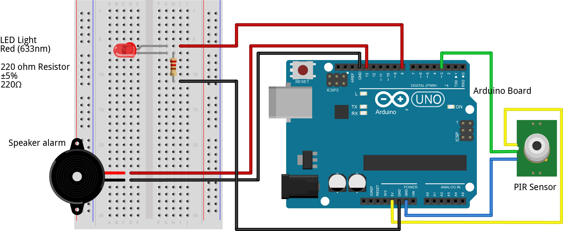
1) Connect LED to breadboard, with each pin across different rows but down the same column. Now connect one pin of your resistor along the same row as a pin of your LED. Connect the other pin of your resistor somewhere along the same column of the first pin. Now connect one wire to your breadboard on the same row as the resistor pin that is on a row by itself. Connect that same wire to a free GND pin on your Arduino. Connect your second cable wire to the other end of the LED and connect it to a numbered pin on the Arduino.
2) Replace the existing code with the code below in the Arduino software.
int BUZZ_Pin = 12; //change to the pin your speaker is connected into
int PIR_Pin = 4; //change to the pin your PIR is connected into
int PIR_State = LOW;
int PIR_Value = 0;
int LED_Pin = 9; //change to the pin your LED is connected into

void setup() {
    pinMode(BUZZ_Pin, OUTPUT);
    pinMode(PIR_Pin, INPUT);
    pinMode(LED_Pin, OUTPUT);
    Serial.begin(9600);
}

void loop() {
    PIR_Value = digitalRead(PIR_Pin);
    if(PIR_Value == HIGH){
    digitalWrite(LED_Pin, HIGH); //turns the LED on when a burglar is detected
      digitalWrite(BUZZ_Pin, HIGH); //turns speaker alarm on
      delay(50);
      digitalWrite(BUZZ_Pin, LOW); //turns speaker alarm off
      delay(50);
      if(PIR_State == LOW){
        Serial.println("Intruder Alert!"); //displays message when a burglar is detected
        PIR_State = HIGH;
      }
    }
    else{
      if(PIR_State = HIGH){
        digitalWrite(LED_Pin, LOW); //turns the LED off when a burglar is detected
        Serial.println("Intruder no longer detected"); //displays message when no burglar is detected
        PIR_State = LOW;
      }
    }
}
3) Change the BUZZ_Pin = __, PIR_Pin = __ and LED_Pin = __ numbers to show the correct pin you plugged your cable from the speaker and the PIR sensor into on the Arduino board.
4) Go Sketch > Verify/Compile to compile the code and save it as “burglaralarm.ino”. Next go Sketch > Upload to send it to your Arduino board. Once this has been completed, and program should return “Done uploading.” The alarm should now sound and the LED should turn on when an intruder is detected! (Yay!)
Power it UP
Once your burglar alarm is fully operational, you can unplug it from the mini-USB cable and make it battery powered using the battery cable and the 9V battery. This allows the burglar alarm to be fully portable, and you can now set it up anywhere you wish!
Nice work! You have finished!
Now hide your burglar alarm close to your valuables!
Not Working? Try This!
- Take the LED out, turn it round, and plug it back in. Does the light work now?
- Check your code.
- Does it compile? If not check the brackets, extra letters etc that are out of place.
- Is it identifying the correct BUZZ_Pin, PIR_Pin and LED_Pin numbers?
- Check the connections on the breadboard.
- Check your breadboard looks like the picture at the end of step 1. If it does and you still do not get words in the window, check that:
- All the pins are pushed in.
- Try using a different LED.
- Try using different cables.
- If none of that gets your light working, ask your teacher/demonstrator for assistance.